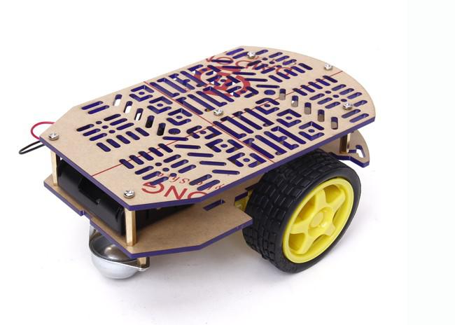
A differential drive mobile robot has a movement based on two separately driven wheels placed on either side of the robot body. Thus, it is able to change its direction by varying the relative rate of rotation of its wheels. The mechanism is very simple since it does not require a steer. This makes this mobile robot very popular.

1. Dynamics
Assume that the robot is able to access and control the angular velocities of its wheels. Let ![]() and
and ![]() denote the angular velocities of right and left wheels, respectively. Usage of stepper motors or closed-loop control of DC motors with optical encoders can achieve this. Thus, the inputs of the robots are
denote the angular velocities of right and left wheels, respectively. Usage of stepper motors or closed-loop control of DC motors with optical encoders can achieve this. Thus, the inputs of the robots are ![]() and
and ![]() . We aim to represent the differential equation which characterizes the positions
. We aim to represent the differential equation which characterizes the positions ![]() and
and ![]() of the center point and heading
of the center point and heading ![]() of the body.
of the body.
The robot has the knowledge of linear velocities of two points on its body owing to the ability to access ![]() and
and ![]() . Figure 1 represents those velocities as
. Figure 1 represents those velocities as ![]() and
and ![]() . Those are
. Those are ![]() and
and ![]() (see: angular velocity). The angular velocity of the robot body is
(see: angular velocity). The angular velocity of the robot body is ![]() (see: rigid body). Using the same identity, the linear velocity of the center point is
(see: rigid body). Using the same identity, the linear velocity of the center point is ![]() . After algebraic manipulations, we derive
. After algebraic manipulations, we derive

Note that ![]() and
and ![]() are the linear velocities of the center point in
are the linear velocities of the center point in ![]() and
and ![]() directions, respectively. The differential drive mobile robot dynamics are given by
directions, respectively. The differential drive mobile robot dynamics are given by
![Rendered by QuickLaTeX.com \begin{equation*}\dot{q}(t) = \left[ \begin{matrix} \dot{\psi}(t) \\ \dot{x}(t) \\ \dot{y}(t) \end{matrix}\right] = \left[\begin{matrix} -\frac{r}{2d} & \frac{r}{2d} \\ \frac{1}{2}r\cos(\psi(t)) & \frac{1}{2}r\cos(\psi(t)) \\ \frac{1}{2}r\sin(\psi(t)) & \frac{1}{2}r\sin(\psi(t)) \end{matrix}\right] \left[\begin{matrix} u_L(t) \\ u_R(t) \end{matrix}\right],\end{equation*}](https://www.ahmettahakoru.com/wp-content/ql-cache/quicklatex.com-07ca0d4a5eb8fc4dbf7a9fb7877f4f56_l3.png)
where ![]() is the heading direction,
is the heading direction, ![]() is the
is the ![]() position,
position, ![]() is the
is the ![]() position,
position, ![]() is the radius of the wheels,
is the radius of the wheels, ![]() is the distance between the wheels,
is the distance between the wheels, ![]() is the angular velocity of the right wheel, and
is the angular velocity of the right wheel, and ![]() is the angular velocity of the left wheel. The same dynamics can be represented in terms of
is the angular velocity of the left wheel. The same dynamics can be represented in terms of ![]() and
and ![]() as
as
(1) ![Rendered by QuickLaTeX.com \begin{equation*}\dot{q}(t) = \left[\begin{matrix} \dot{\psi}(t) \\ \dot{x}(t) \\ \dot{y}(t) \end{matrix}\right] =\left[\begin{matrix} 1 & 0 \\ 0 & \cos(\psi(t)) \\ 0 & \sin(\psi(t)) \end{matrix}\right] \left[\begin{matrix} w(t) \\ v(t) \end{matrix}\right].\end{equation*}](https://www.ahmettahakoru.com/wp-content/ql-cache/quicklatex.com-e1ccd9547a1b865af4615863a5df394b_l3.png)
2. Control
The system in (1) has a special structure ![]() where
where ![]() ,
, ![]() , and
, and ![]() . The systems of this form are \emph{nonholonomic control systems}. Although the system in (1) is controllable; yet, there exists no continuous feedback law that stabilizes the origin
. The systems of this form are \emph{nonholonomic control systems}. Although the system in (1) is controllable; yet, there exists no continuous feedback law that stabilizes the origin ![]() . Please see the detailed discussion in Chapter 4.2 of [1].
. Please see the detailed discussion in Chapter 4.2 of [1].
Theorem (see Corollary 4.2 in [1]). The system in (1) cannot be asymptotically stabilized by a continuous feedback law.
Dr. Liberzon offers a switching control approach to stabilize the origin (or any set-point ![]() ) in [1].
) in [1].
3. Simulation
4. References
[1] Liberzon, D. (2003). Switching in systems and control. Springer Science & Business Media.

